1. Flowchart Pseudocode
2. Pseudocode
A flow chart is a schematic representation of a process..
Flow-charts can be created by hand or manually in most office software, but lately specialized diagram drawing software has emerged that can also be used for the purpose, such as Visio, OpenOffice.org Draw, ConceptDraw, Dia, SmartDraw, and OmniGraffle.
| |
Flowcharts may contain other symbols, such as connectors, usually represented as circles, to represent converging paths in the flow chart. Circles will have more than one arrow coming into them but only one going out. Some flow charts may just have an arrow point to another arrow instead. These are useful to represent an iterative process (what in Computer Science is called a loop). A loop may, for example, consist of a connector where control first enters, processing steps, a conditional with one arrow exiting the loop, and one going back to the connector
Pseudocode
Pseudocode (derived from pseudo and code) is a description of a computer programming algorithm that uses the structural conventions of programming languages, but omits detailed subroutines or language-specific syntax. It can also refer to a high level 'language' whose aim is to generalise the logic and program flow of a computer program
In the context of the Short Code language, pseudocoding refer to the use of codes to represent assembly instructions, even though such codes could not be automatically compiled into an executable program. This usage has mostly fallen out of use.
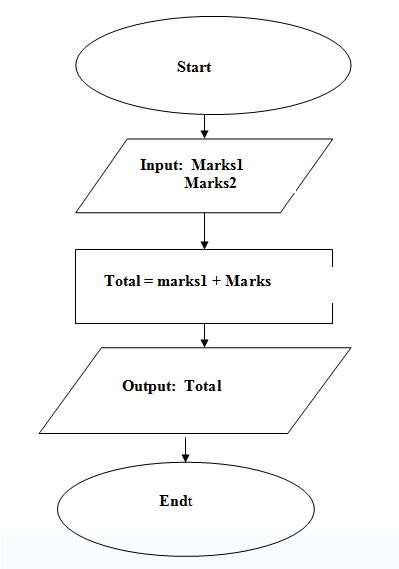
Program for adding two numbers using Pseudocode
Begin
Input: first number and second number
Total = first Number + Second Number
Output: Total
End
.
No comments:
Post a Comment